
THERMOFORMING & VACUUM FORMING MOLDS
We Design the Mold in NX. Then Machine It In-House.
Send your completed 3D part model. We develop the tooling geometry and program the toolpaths in NX CAM here in our workshop.
Founded in 2006 · Hengli, Dongguan · Maximum mold size: 4000 × 2800 × 1200 mm
 Siemens NX / UG
Tooling Geometry for Forming and Machining.
We develop the mold model in Siemens NX with the forming requirements, cutting tools and setup in mind.
- Develop the forming surfaces from the part geometry
- Apply shrinkage compensation and define parting geometry where required
- Plan for tool access, machining allowance and workholding
- Plan the machining sequence and program the toolpaths in NX CAM
Common tooling materials: tooling board, machined aluminum, cast aluminum and cast iron. For other materials, send the final 3D part model and requirements for review.
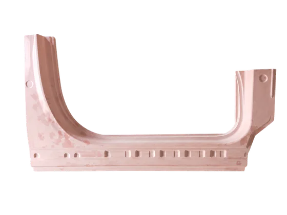
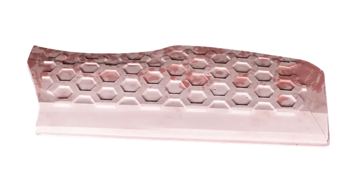
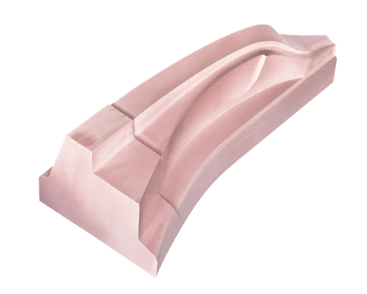
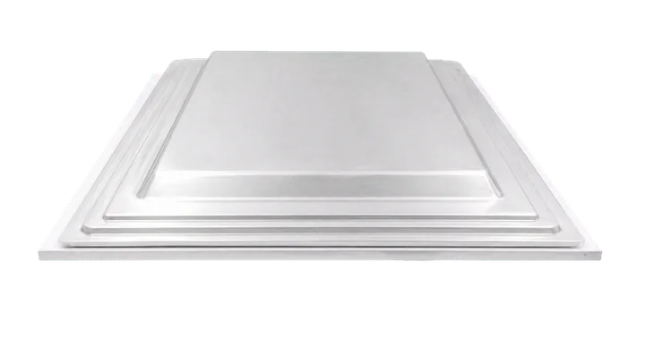
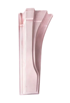
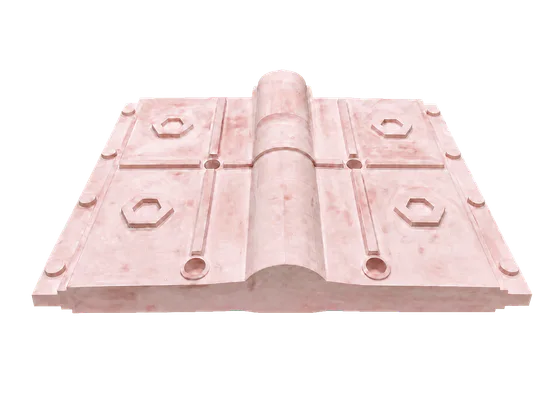
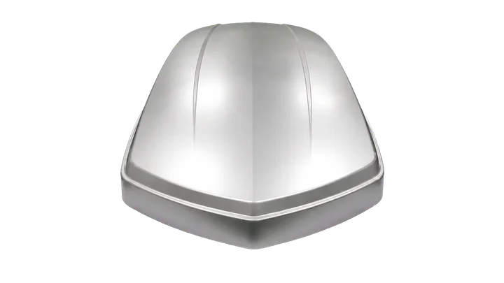
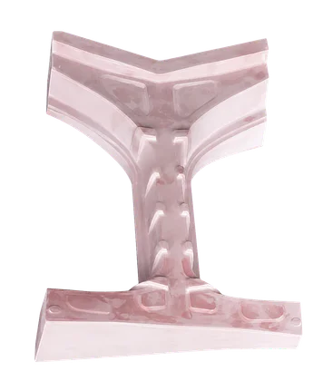
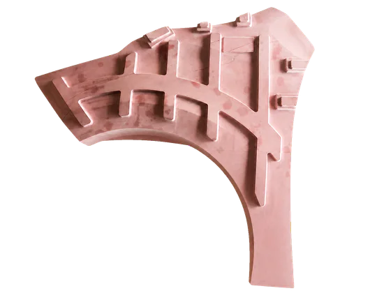
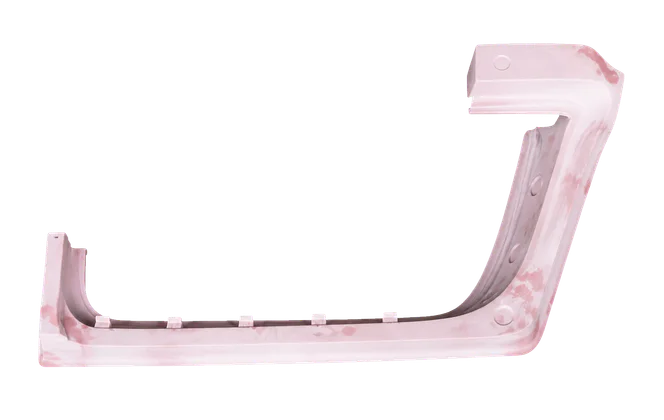
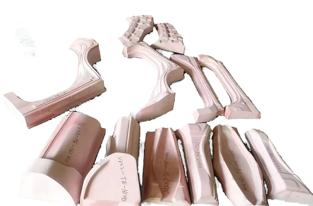
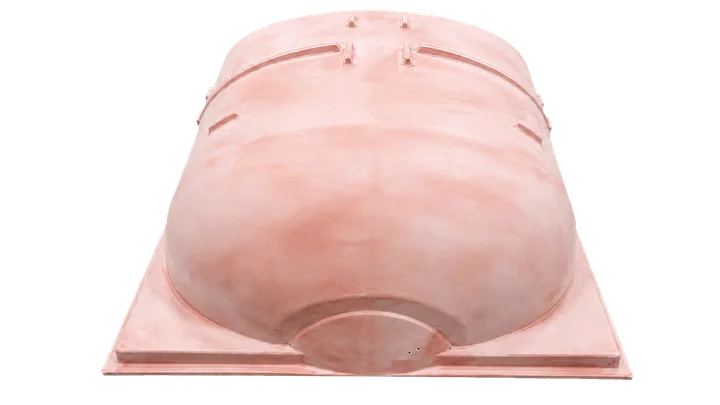
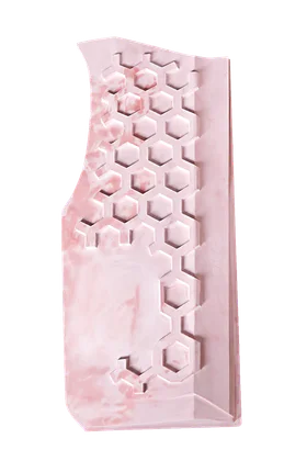
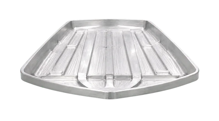
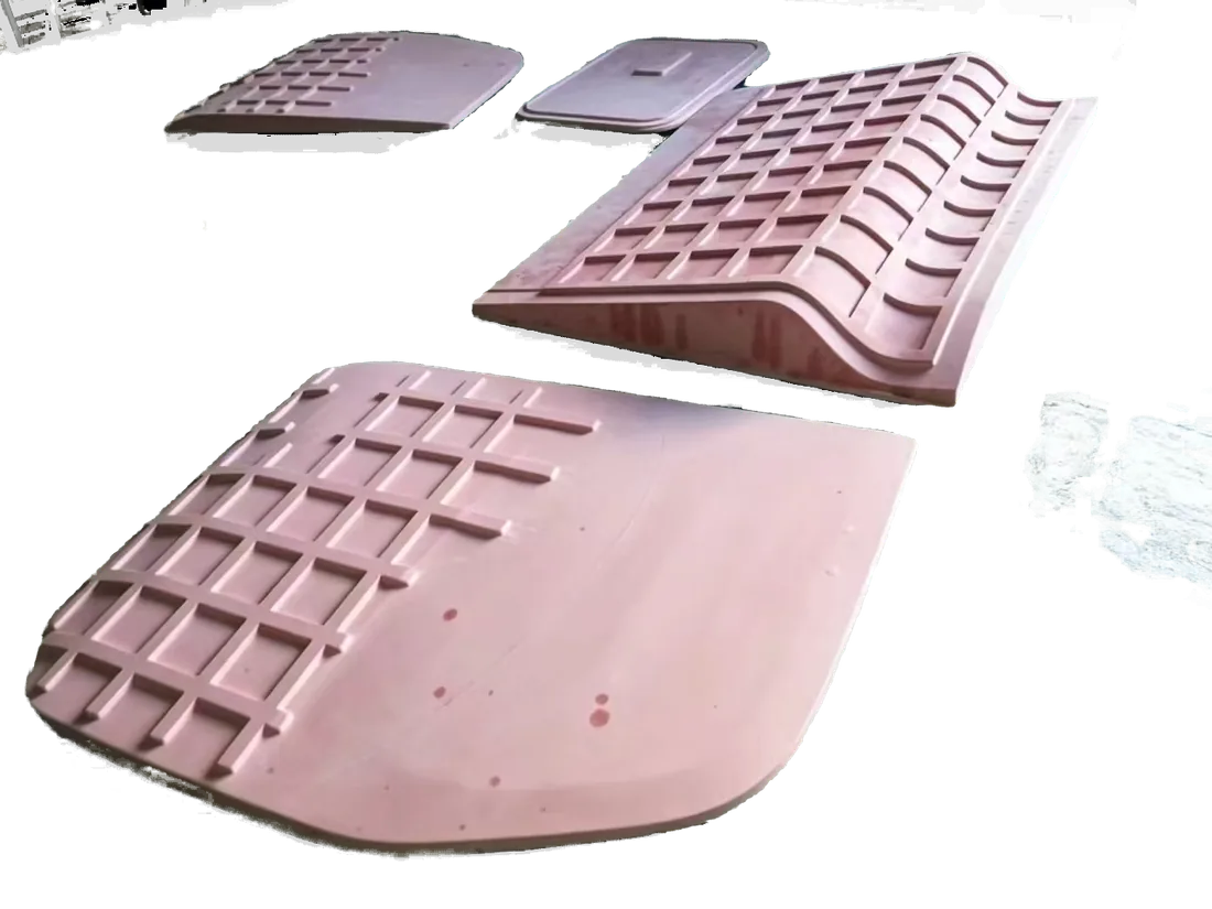
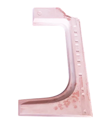
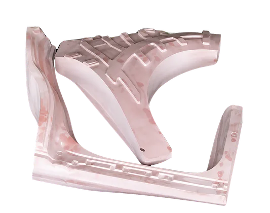
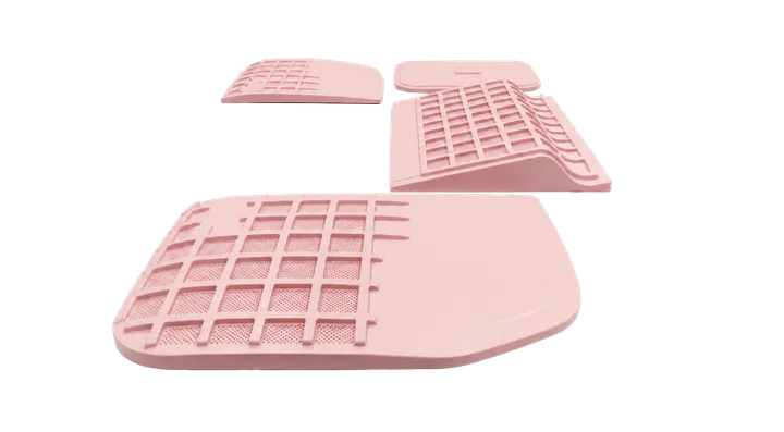
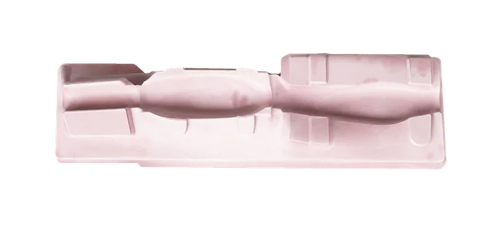
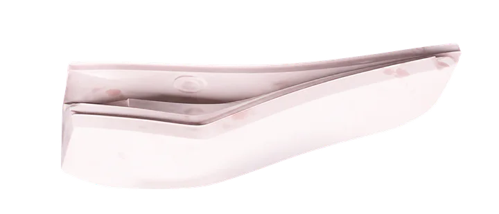
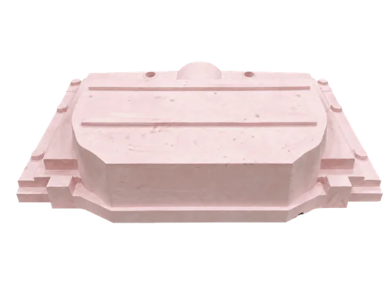
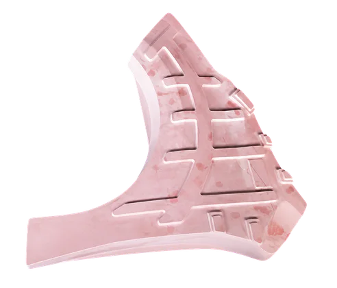
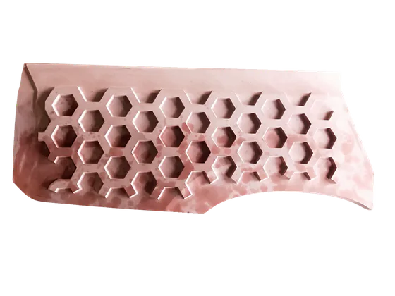
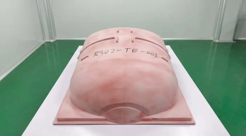
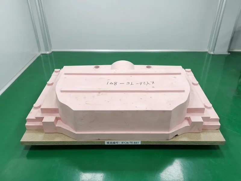
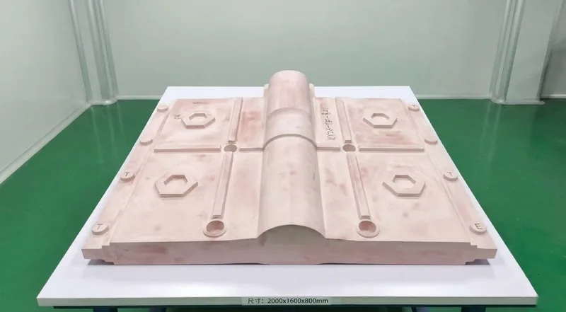
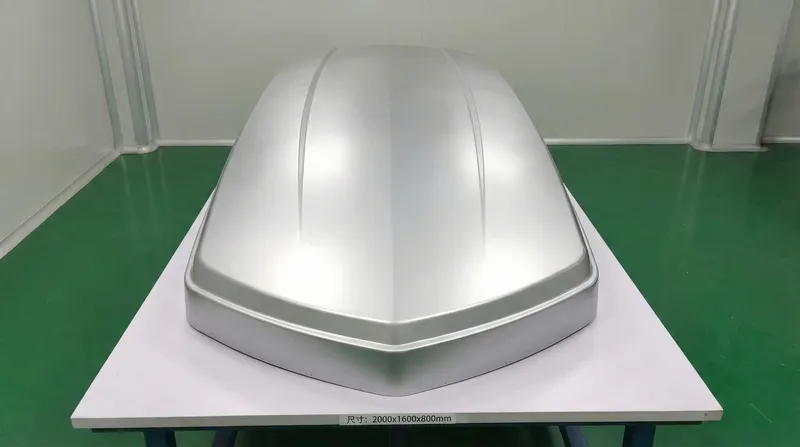
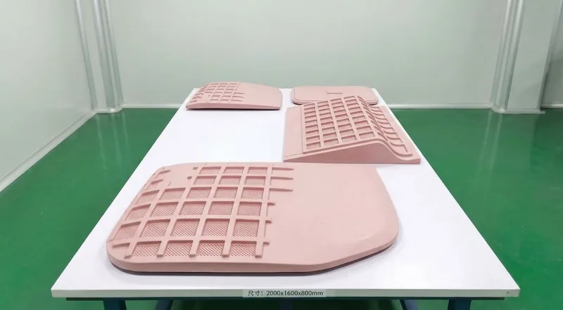
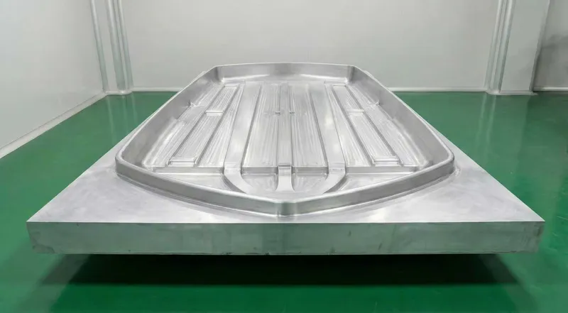
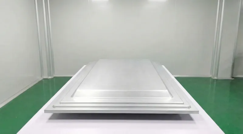
Molds Made In-House
Reference Sizes
L × W × H / mm
Reference sizes, not measurements of the molds pictured.
Selected Customers & Projects
-
 Aviation Project
-
 Automotive Project
- 顺丰速运SF EXPRESS Drone Project
-
 Automotive Line Guarding · USA

DIRECT ACCESS TO AN ENGINEER
Talk Through the Tooling with an Engineer.
Discuss your forming requirements and any critical dimensions or features with the engineer handling your project.
Send Us the Final 3D Part Model.
We accept NX/UG and STEP files. Once we receive the final 3D part model and project requirements, we will confirm within one business day whether we can take on the project.
Send Your 3D Part Model